TempDiff
TempDiff is an arduino based tool which visually indicates the temperature difference between two zones with a simple visual signal. I built TempDiff a couple years ago and it's been hanging on my wall since.
The original motivation for TempDiff was to easily determine if it was time to open or close my windows in the summer. My house is well insulated so I can often make it deep into the summer without using the A/C. What I do is open the windows when it is colder at night and immediately shut them in the morning. One problem with this strategy is that if you leave the windows open for even an hour too long, the house heats up fast. TempDiff addresses this by adjusting the color and brightness of a multi-color LED. This LED is easily seen in the room it's in, prompting the user to take action.
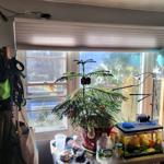
TempDiff casually hangs by my door, in the top left of the photo, shining blue indicating that it is cooler inside than out.
Components
TempDiff is pretty simple with only a handful of components:
When I build projects like this, no matter how straight forward they are, I write standalone sketches to test each component on a bread board.
DHT22
The DHT22 has 3 pins: voltage, ground and data. The voltage pin is connected to the 3.5 or 5 volts on the Arduino. Ground to ground on the Arduino. Data to a digital pin on the Arduino.
With the DHT Sensor Library it is easy to use.
#include <DHT.h>
#define DHT_PIN 8
#define DHTTYPE DHT22
DHT dht(DHT_PIN, DHTTYPE);

void setup() {
  Serial.begin(9600);
  dht.begin();
}

void loop() {
  Serial.print("Temperature: ");
  Serial.print(celciusToFahrenheit(dht.readTemperature()));
  Serial.print(", Humidity: ");
  Serial.print(dht.readHumidity());
  Serial.print("\n");
  delay(1000);
}

float celciusToFahrenheit(float c) {
  return (c * 1.8) + 32;
}
I have read a lot of complaints about the DHT22's accuracy online. I did quite a bit of testing to see how accurate the temperatures were. They were accurate enough for my use case, maybe +/- 2 degrees, possibly better unfortunately I did not hold onto this data long term.
RGB LED
The RGB LED's are also simple to use. They have 4 pins one for each color: red, green, blue and one for ground. You connect the color pins to digital pins on the arduino and the ground to ground.
int RED_PIN = 2;
int GREEN_PIN = 3;
int BLUE_PIN = 4;

void setup() {

}

void loop() {
  color(255, 0, 0);
  delay(500);
  color(0, 255, 0);
  delay(500);
  color(0, 0, 255);
  delay(500);
}


void color(int r, int g, int b) {
  analogWrite(RED_PIN, r);
  analogWrite(GREEN_PIN, g);
  analogWrite(BLUE_PIN, b);
}
Display
I didn't initially have a display attached to TempDiff. But once I was using it for a while I realized it would be helpful to see the detected temperatures. For example, if it the LED is red meaining it's warmer inside than out, I may want to open the window, but if it's 55 degrees inside and 50 degress outside, I probably will decide not to.
I used the Adafruit GFX Library for initial testing of the display, but I noticed that was taking up 26% of program space on my UNO, which was excessive. When I went to combine all these components together I was getting a little too close to comfort for the size limit. Especially because I wanted to add other stuff in the future. Truthfully, I didn't really need any of the features Adafruit GFX offered, I just needed to write text to the screen, ideally in a simple way. I found SSD1306Ascii library which worked great and still had a great interface, but took up almost half the size (14%).
The OLED displays communicate with the arduino via I2C. I2C is a protocol which allows a parent device to communicate with one or more child devices. While it didn't come into play for this project this parent -> children relationship can be very cool. I am currently building a fish tank monitoring / control system which has numerous waterproof temperature probes attached to it. If I was using DHT22's it would require a data pin for each probe. But these waterproof probes support I2C meaning I can have many of them while only taking up to 2 pins on the Arduino. It also makes physically easier to chain across the back of the fish tank, as I am able to daisy chain the devices instead of having an individual wire running from each child device to the parent controller. But more details about that in a future post.
Basically, the display has a pin labeled SDA which goes into A4 on the Arduino UNO, and a pin label SCL which goes into A5. The specific pins you use are dependent on which Arduino you have. I verified the display worked with this:
// For OLED Display UCT-60262
// All from: https://github.com/greiman/SSD1306Ascii
// Which has much lower memory foot print when compared to Adafruit Libs which caused instability
#include <Wire.h>
#include "SSD1306Ascii.h"
#include "SSD1306AsciiWire.h"
#define I2C_ADDRESS 0x3C
SSD1306AsciiWire display;

void setup() {
  display.begin(&Adafruit128x64, I2C_ADDRESS);
  display.setFont(Adafruit5x7);
  display.set2X();
}

void loop() {
  display.clear();
  display.println("Hello");
  display.println("World");
}
If you run this sketch you will notice that the screen continuously flashes. I used this sketch simply to confirm that the display was working. In the final program I have a delay(5000) at the end of every loop meaning the screen refreshes every 5 seconds. I found this acceptable. In other applications I haven't and wanted minimal screen flashing. This particular library provides functions to manipulate the screen in more specific ways. Additionally, if you are just displaying different words based on some inner state, you could create a buffer to store the words displayed and only call display.clear() when the buffer changes.
Putting it all together
Now I put all the code together adding logic in the loop function to compare the two temperatures and adjust the LED accordingly.
// For DHT22 sensores
#include <DHT.h>
#define INDOOR_DHT_PIN 7
#define OUTDOOR_DHT_PIN 8
#define DHTTYPE DHT22
DHT indoorDHT(INDOOR_DHT_PIN, DHTTYPE);
DHT outdoorDHT(OUTDOOR_DHT_PIN, DHTTYPE);

// Temperature diff LED pins
#define TEMPERATURE_RED_PIN 3
#define TEMPERATURE_GREEN_PIN 5
#define TEMPERATURE_BLUE_PIN 6

// For OLED Display UCT-60262
// All from: https://github.com/greiman/SSD1306Ascii
// Which has much lower memory foot print when compared to Adafruit Libs which caused instability
#include <Wire.h>
#include "SSD1306Ascii.h"
#include "SSD1306AsciiWire.h"
#define I2C_ADDRESS 0x3C
SSD1306AsciiWire display;

void setup() {
  Serial.begin(9600);

  indoorDHT.begin();
  outdoorDHT.begin();

  display.begin(&Adafruit128x64, I2C_ADDRESS);
  display.setFont(Adafruit5x7);
  display.set2X();
}

void loop() {
  Serial.print("**** **** **** ****\n");

  // On Temperature LED, display:
  // - off, when temperatures inside and out are the same
  // - red, when it is warmer inside than outside
  // - blue, when it is cooler inside than outside
  float indoorTemp = measureDHTTemp(indoorDHT);
  Serial.print("indoor temp: ");
  Serial.print(indoorTemp);
  Serial.print("\n");

  float outdoorTemp = measureDHTTemp(outdoorDHT);
  Serial.print("outdoor temp: ");
  Serial.print(outdoorTemp);
  Serial.print("\n");

  float tempDiff = indoorTemp - outdoorTemp;
  Serial.print("tempDiff: ");
  Serial.print(tempDiff);
  Serial.print("\n");

 if (tempDiff < 0) {
    colorTemperature(0, 0, abs(tempDiff * 4));
  } else if (tempDiff > 0) {
    colorTemperature(abs(tempDiff * 4), 0, 0);
  } else {
    colorTemperature(0, 0, 0);
  }

  Serial.print("\n");

  // Print temps to OLED display
  display.clear();
  display.println(" In: " + String(cToF(indoorTemp)));
  display.println("Out: " + String(cToF(outdoorTemp)));

  delay(5000);
}

float cToF(float c) {
  return (c * 1.8) + 32;
}

void measureIndoor() {
  measureDHT("INDOOR", indoorDHT);
}

void measureOutdoor() {
  measureDHT("OUTDOOR", outdoorDHT);
}

float measureDHTTemp(DHT dht) {
  return dht.readTemperature();
}

float measureDHTHumidity(DHT dht) {
  return dht.readHumidity();
}

void measureDHT(String name, DHT dht) {
  float humidity = dht.readHumidity();
  float temperature = dht.readTemperature();
  Serial.print(name + " - ");
  Serial.print("Humidity: ");
  Serial.print(humidity);
  Serial.print(" %, Temp: ");
  Serial.print(celciusToFahrenheit(temperature));
  Serial.println(" Fahrenheit");
}

void colorTemperature(int r, int g, int b) {
  analogWrite(TEMPERATURE_RED_PIN, r);
  analogWrite(TEMPERATURE_GREEN_PIN, g);
  analogWrite(TEMPERATURE_BLUE_PIN, b);
}

float celciusToFahrenheit(float c) {
  return (c * 1.8) + 32;
}
Assembly
The case I built for TempDiff is a little uhhhhhhh eccentric. When I build arduino projects that I want to use long term I really like to expose the electronics so that visitors can see them. In my head this could lead to magical moments where I teach a friend how this stuff works. In reality, the only time a friend has ever acknowledged TempDiff hanging on my wall is with the comment "so what is that? A bomb?".
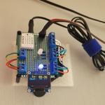
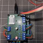
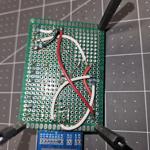
I 3D printed a base and mounted the arduino on it, then I built a floating PCB "shield" which attached to the arduino. The final result looks like this:
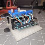
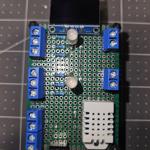
I guess I get where my friend was coming from with the bomb comparison :D
I still think this assembly is kinda neat tho, electronics just totally raw and exposed. The 3D printed base is made with a "transparent" filament, which I could never get to print very transparently. My originally idea was to make a case ala see-through gameboys and N64 controllers.
You might notice there is a second LED not mentioned in the code or anywhere above. I was originally going to compare the indoor/outdoor humidity as well, but I didn't really find the information useful in practice. I plan on repurposing this LED during future modifications.
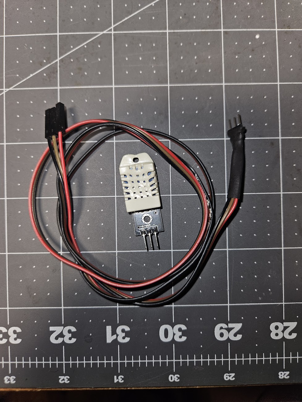
I hacked together a long cable for the outdoors DHT22. Notice how the one in the pic is partially melted? I accidentally melted it while testing the DHT22 with a lighter. The white part is just an outer case tho, as far as I can tell the actual sensor wasn't damaged. This thing has been hanging out of my window thru rain, snow and sun for over 2 years now. It still works and reports temperatures similar to another commercial outdoor temperature gauge I have setup nearby. Surprisingly durable in my opinion.
An Emergent Use Case
As I mentioned at the start of this post, the original intention of TempDiff was to tell me when to open and close windows in the summer but as it has hung on my wall for 8 seasons I have found it useful in other ways.
I have a ton of house plants, in the summer I keep some of them outside and others in front of different windows in my home. In the winter I group them all together in front of the window you can see in the first photo in this post. I then put a grow light over them. I have found that when the sun is pointing directly at the window, and thus directly at the outdoor DHT22, the detected temperature rises a lot. During this period of direct sunlight, TempDiff will indicate that it is cooler inside than outside. This is a false signal with respect to my initial intention, but in the context of winter it provides important information. In the winter I try to keep my thick blinds down as much as possible. When TempDiff turns blue like this it indicates a window of time where I can open the blind, exposing houseplants and often times my dog to some much needed direct sunlight without letting too much cold into the house.
Future Improvements
I added the OLED display to TempDiff because I found it was necessary to know what the actual indoor temperature is. I would prefer not to have the OLED or at least not rely on it. The goal of this project was a simple visual indicator that can be seen at a glance. Having to walk up to read the text on the tiny screen invalidates that goal. I would like to utilize the second LED to indicate where the indoor temperature is with respect to a specfic set point. So for example, I might make that setpoint 66 degrees. If it is 66 +/- 1 degrees inside maybe the second LED turns on.
I would also like to replace the Arduino UNO with an Arudino IOT so I can feed the temperature data to other DIY IOT devices I have in my house. Specifically my home dashboard (which I will outline in a different post someday), could display both the inside and outdoor temperatures.