Arduino Wi-Fi Switch
A Warning
👏 THIS IS NOT A TUTORIAL 👏 YOU SHOULD NOT PLAY WITH 120V POWER UNLESS YOU KNOW WHAT YOU ARE DOING 👏
My goal in publishing this article is as a demonstration and to share with like minded people. If you can draw inspiration from this for your own project, that's great! If you are reading this as a blueprint for your first ever project with an Arduino, please reconsider.
I think there is a lot of fear mongering that goes on with electricity. People seem to think it's magic and it treat it as such. I have shocked myself many times, I don't encourage it and I like to think I now act with the appropriate level of caution to do so safely.
The first time I very briefly hit with 120V was when I was very young. I stuck a fork into an outlet. I wanted to see what happened. I was aware of the risks to some extent so I attached the fork to a ruler. I saw, but unexpectedly, I also felt. Fortunately, I was fine.
When I was a tween I took apart a TV and got shocked by a huge capacitor inside it. I didn't even know what a capictor was, luckily the TV had been unplugged for days and the capacitor had mostly discharged. If you are messing with stuff like this, don't be like me. Do the research, know the risks of everything you are touching.
 A 1970's safey poster I printed out.
🙏 THANK YOU 🙏
Background and Inspiration
I wanted a Wi-Fi controlled switch for 120V appliances for a long time. I thought my requirements were simple:
- Switch should be toggleable via HTTP.
- Switch should not require an account with the manufacturer.
- Swithc should not require an app for configuration.
- Switch should not communicate with external servers.
- Switch should be well documented.
When I search "wifi switch" on Amazon right now I get over 1000 results, all the products on the first page have over 4 star ratings. None of these products meet my requirements, or at the very least it is impossible to tell if they do based on the poorly written and often ambiguous descriptions associated with their Amazon listings.
Perhaps there is an easy answer here, a product that does respect my requirements, but I could not find it. I did however, in a search last March, come across this 2-Channel 120V Relay with 5V DC Power Supply. My interest was piqued and I bought one.
The Relay
The idea with this relay is that you can power an arduino or something like it with the 5V DC and control the relays from that device. This sounded like the outline of a DIY Wi-Fi switch to me.
One problem, all too common on Amazon, is that the relay did not come with documentation and many reviewers reported that their device did not work. There was one reviewer who used a multimeter to reverse engineer the layout of the device which they shared in their review. With this knowledge, I felt confident that unless I received a truly broken board I could get it working.
The layout of the board looks like this:
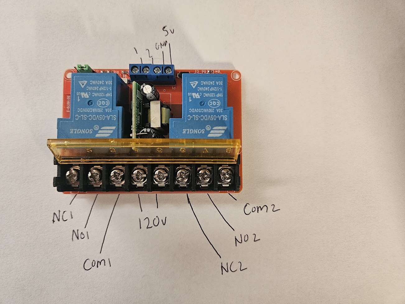
On the left and right sides of the front terminal there are Normally Closed, Normally Open and Commmon slots for each relay. In the middle is the 120V power supply, polarity does not matter.
In the back are two terminals that control wether a relay is on or off along with 5Vs and Ground to power an Arduino. The control terminals are react to LOW or HIGH signals, I was able to quickly verify my board worked by connecting 120V to the front middle and then running a cable from the back 5V slot to the two control terminals. I could hear the relays click on and off, we were in business.
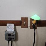
I think a lot of the confusion surrounding this device comes from a misunderstanding of the 120V supply. This 120V supply powers the relays and Arduino but does not provide any power to the whatever device you hook up to the relays. So for example, if you wanted to hook up a light to this relay you would need to wire it like this:
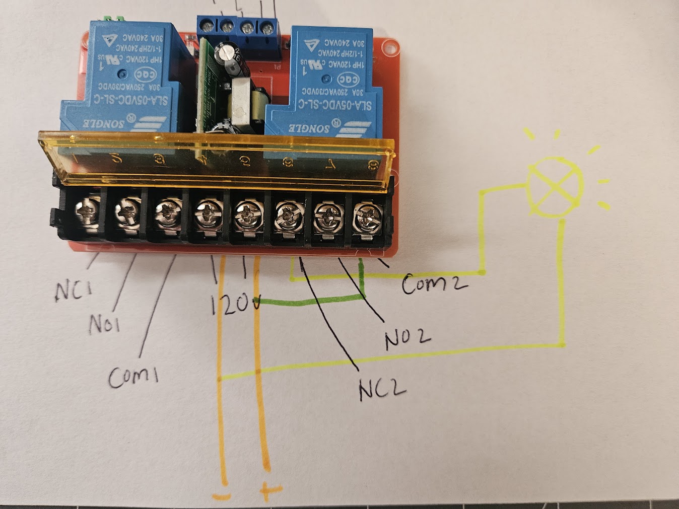
In this configuration the light would shine when the relay 2 terminal is HIGH and would turn off when that same terminal is LOW.
Building the Switch
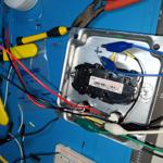
With a confirmed working relay, I got to building out my switch. I decided on using an Arduino IOT 33 to control the relays. The idea being that I would run an HTTP server on the Arduino and make it react to GET requests to toggle the relays. In addition to HTTP control, there also needed to be physical switches which could toggle the relays. I decided to use a 2 Gang Metal Box as the housing. I then got to building. Unfortunately I didn't take many progress pics but here are few:
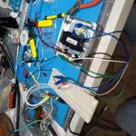
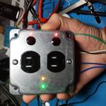
On the front you can see 4 status lights. The two red lights indicate wether the corresponding switch is on or off. The orange and green lights indicate the status of the WiFi connection. Knowing that everything was working, I wired everything up and forced it into a box.
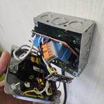
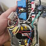
Above you can see the final assembly and then insides spilling out of the box. I definitely wish I used a bigger box and somehow exposed the USB connector on the Arduino externally. Getting back into this thing to update the code is needlessly annoying. But otherwise, I have been using this thing for about 6 months now with no issue.
The Code
The sketch I currently have running is:
int STATUS_PIN = LED_BUILTIN;
int RELAY_1_PIN = 2;
int RELAY_2_PIN = 3;
int ON_STATUS_PIN = 8;
int CONNECTED_STATUS_PIN = 9;
int RELAY_1_STATUS_PIN = 4;
int RELAY_2_STATUS_PIN = 5;

int TOGGLE_RELAY_1_BUTTON_PIN = 6;
int TOGGLE_RELAY_2_BUTTON_PIN = 7;

#include<ezButton.h>
ezButton toggleRelay1Button(TOGGLE_RELAY_1_BUTTON_PIN);
ezButton toggleRelay2Button(TOGGLE_RELAY_2_BUTTON_PIN);

// wifi setup
#include <WiFiNINA.h>
char ssid[] = "*****"
char pass[] = "*****"
int keyIndex = 0;
int status = WL_IDLE_STATUS;
WiFiServer server(80);
WiFiClient client = server.available();

void setup() {
  pinMode(STATUS_PIN, OUTPUT);
  pinMode(RELAY_1_PIN, OUTPUT);
  pinMode(RELAY_2_PIN, OUTPUT);

  // status LEDs
  pinMode(ON_STATUS_PIN, OUTPUT);
  pinMode(CONNECTED_STATUS_PIN, OUTPUT);
  pinMode(RELAY_1_STATUS_PIN, OUTPUT);
  pinMode(RELAY_2_STATUS_PIN, OUTPUT);

  toggleRelay1Button.setDebounceTime(10);
  toggleRelay2Button.setDebounceTime(10);

  Serial.begin(9600);

  updateStatusLight(ON_STATUS_PIN, true);
  updateStatusLight(CONNECTED_STATUS_PIN, false);
  updateStatusLight(RELAY_1_STATUS_PIN, false);
  updateStatusLight(RELAY_2_STATUS_PIN, false);

  digitalWrite(STATUS_PIN, LOW);

  enable_WiFi();
  connect_WiFi();

  server.begin();
  printWifiStatus();
}


void printWifiStatus() {
  // print the SSID of the network you're attached to:
  Serial.print("SSID: ");
  Serial.println(WiFi.SSID());

  // print your board's IP address:
  IPAddress ip = WiFi.localIP();
  Serial.print("IP Address: ");
  Serial.println(ip);

  // print the received signal strength:
  long rssi = WiFi.RSSI();
  Serial.print("signal strength (RSSI):");
  Serial.print(rssi);
  Serial.println(" dBm");

  Serial.println(WiFi.firmwareVersion());

  Serial.print("To see this page in action, open a browser to http://");
  Serial.println(ip);
}

void enable_WiFi() {
  // check for the WiFi module:
  if (WiFi.status() == WL_NO_MODULE) {
    Serial.println("Communication with WiFi module failed!");
    // don't continue
    while (true);
  }

  String fv = WiFi.firmwareVersion();
  if (fv < "1.0.0") {
    Serial.println("Please upgrade the firmware");
  }
}

void connect_WiFi() {
  // attempt to connect to Wifi network:
  while (status != WL_CONNECTED) {
    Serial.print("Attempting to connect to SSID: ");
    Serial.println(ssid);

    // Connect to WPA/WPA2 network. Change this line if using open or WEP network:
    status = WiFi.begin(ssid, pass);

    waitForConnection();
  }
}

void waitForConnection() {
  // 10 seconds, flash green light
  for (int i = 0; i < 20; i++) {
    if (i % 2 == 0) {
      updateStatusLight(CONNECTED_STATUS_PIN, true);
    } else {
      updateStatusLight(CONNECTED_STATUS_PIN, false);
    }
    delay(500);
  }
}

void loop() {
  status = WiFi.status();

  if (status != WL_CONNECTED) {
    updateStatusLight(CONNECTED_STATUS_PIN, false);
    connect_WiFi();
  } else {
    updateStatusLight(CONNECTED_STATUS_PIN, true);
  }

  client = server.available();
  if (client) {
    handleServer();
  }

  handlePhysicalButtons();

  updateStatusLight(RELAY_1_STATUS_PIN, digitalRead(RELAY_1_PIN));
  updateStatusLight(RELAY_2_STATUS_PIN, digitalRead(RELAY_2_PIN));
}

void updateStatusLight(int pin, bool on) {
  int brightnessOn = 2;
  int greenBrightness = 1;
  if (on) {
    if (pin == CONNECTED_STATUS_PIN) {
      analogWrite(pin, greenBrightness);
    } else {
      analogWrite(pin, brightnessOn);
    }
  } else {
    analogWrite(pin, 0);
  }
}

void handlePhysicalButtons() {
  toggleRelay1Button.loop();
  toggleRelay2Button.loop();

  if (toggleRelay1Button.isPressed()) {
    digitalWrite(RELAY_1_PIN, !digitalRead(RELAY_1_PIN));
    Serial.println("Relay 1 activated with button");
  }

  if (toggleRelay2Button.isPressed()) {
    digitalWrite(RELAY_2_PIN, !digitalRead(RELAY_2_PIN));
    Serial.println("Relay 2 activated with button");
  }
}

void handleServer() {

  if (client) {                             // if you get a client,
    Serial.println("new client");           // print a message out the serial port
    String currentLine = "";                // make a String to hold incoming data from the client
    while (client.connected()) {            // loop while the client's connected
      if (client.available()) {             // if there's bytes to read from the client,
        char c = client.read();             // read a byte, then
        //Serial.write(c);                    // print it out the serial monitor
        if (c == '\n') {                    // if the byte is a newline character

          // if the current line is blank, you got two newline characters in a row.
          // that's the end of the client HTTP request, so send a response:
          if (currentLine.length() == 0) {

            // HTTP headers always start with a response code (e.g. HTTP/1.1 200 OK)
            // and a content-type so the client knows what's coming, then a blank line:
            client.println("HTTP/1.1 200 OK");
            client.println("Content-type:text/html");
            client.println();

            // The HTTP response ends with another blank line:
            client.println();
            // break out of the while loop:
            break;
          }
          else {      // if you got a newline, then clear currentLine:
            currentLine = "";
          }
        }
        else if (c != '\r') {    // if you got anything else but a carriage return character,
          currentLine += c;      // add it to the end of the currentLine
        }

        if (currentLine.endsWith("GET /1/ON")) {
          digitalWrite(RELAY_1_PIN, HIGH);
          Serial.println(currentLine);
        }
        if (currentLine.endsWith("GET /1/OFF")) {
          digitalWrite(RELAY_1_PIN, LOW);
          Serial.println(currentLine);
        }

        if (currentLine.endsWith("GET /2/ON")) {
          digitalWrite(RELAY_2_PIN, HIGH);
          Serial.println(currentLine);
        }
        if (currentLine.endsWith("GET /2/OFF")) {
          digitalWrite(RELAY_2_PIN, LOW);
          Serial.println(currentLine);
        }

      }
    }
    // close the connection:
    client.stop();
    Serial.println("client disconnected");
  }
}
The code for this project is primarily based on WiFiNINA sample code which you can see here.
Originally, the only changes I made were to add relay control logic to the handlerServer function. For example:
if (currentLine.endsWith("GET /1/ON")) {
    digitalWrite(RELAY_1_PIN, HIGH);
    Serial.println(currentLine);
}
Turns on Relay 1 when the Arduino recieve a GET request at /1/ON.
I also reflected the internet connection by using updateStatusLight where needed.
After running the switch for a week or so I noticed it would disconnect from WiFi frequently. I researched this issue and realized I had out of date firmware. I updated the firmware and it worked better, but it would still disconnect, maybe 3 times a week and never reconnect. So I added retry logic which starts in loop with:
if (status != WL_CONNECTED) {
  updateStatusLight(CONNECTED_STATUS_PIN, false);
  connect_WiFi();
} else {
  updateStatusLight(CONNECTED_STATUS_PIN, true);
}
Basically, I just keep trying over and over again until finally connected. I would say once or twice a week I randomly walk by and see the green light is blinking meaning the Arduino is attempting to connect to my WiFi. Strangely, this has never effected my useage of the device. It is connected often enough that it always works when I need it.
I am building another Arduino IOT project right now. While I am planning on reusing most of this code I would like to make one key improvement. Currently, when the Arduino is reconnecting or connecting for the first time it blocks the execution of the entire program for 10 seconds (see waitForConnection). This means that when disconnected, the physical buttons don't work. They should work so that is what I will be focused on.
One other housekeeping item I should mention is I DO NOT have this switch exposed the outside internet. This is not a secure connection, it's HTTP, I wouldn't be surprised if the client.read functions are vulnerable to overflow attacks of some kind. It is exposed to my local network only which suits my purposes but may not suit yours. I should also mention the Arduino has been assigned a static IP on from my router, which means it will not change IPs after losing power.
This switch is currently used as part of my insane alarm clock, which which you can read about here. 10 minutes before my alarm clock goes off it triggers this switch which turns on my electric water heater. Theoretically leading to me waking up and already having boiling water for my pour over coffee. Here is a quick video of me demonstrating the switch in action: